What can be cooked from squid: quick and tasty
) for a single deep ground electrode based on modular grounding is performed as a calculation of a conventional vertical ground electrode made of a metal rod with a diameter of 14.2 mm.
The formula for calculating the grounding resistance of a single vertical ground electrode system:
where:
ρ - soil resistivity (Ohm * m)
L - length of the earthing switch (m)
d - diameter of the ground electrode (m)
T - deepening of the ground electrode (distance from the surface of the earth to the middle of the ground electrode)(m)
π - mathematical constant Pi (3.141592)
ln - natural logarithm
For electrolytic grounding by ZANDZ, the formula for calculating grounding resistance is simplified to the following form:
- for ZZ-100-102 kit
The contribution of the connecting earth conductor is not taken into account here.
Distance between grounding electrodes
With a multi-electrode configuration of the ground electrode system, another factor begins to influence the final grounding resistance - the distance between the grounding electrodes. In the formulas for calculating grounding, this factor is described by the "utilization factor" value.
For modular and electrolytic grounding, this coefficient can be neglected (i.e., its value is 1), provided that a certain distance between the grounding electrodes is observed:
- not less than the immersion depth of the electrodes - for modular
- not less than 7 meters - for electrolytic
Connection of electrodes to the ground electrode
To connect the grounding electrodes to each other and to the object, copper wire rod or steel strip is used as a grounding conductor.
The conductor cross-section is often chosen - 50 mm² for copper and 150 mm² for steel. It is common to use conventional 5 * 30mm steel strip.
For a private house without lightning rods, it is enough copper wire section 16-25 mm².
More information about laying the grounding conductor can be found on the separate page "Grounding".
Service for calculating the probability of a lightning strike into an object
If, in addition to the grounding device, you have to install an external lightning protection system, you can use a unique service for calculating the probability of a lightning strike into an object protected by lightning rods. The service was developed by the ZANDZ team together with the JSC "Energy Institute named after G.M. Krzhizhanovsky" (JSC "ENIN")
This tool allows not only to check the reliability of the lightning protection system, but also to carry out the most rational and correct lightning protection project, providing:
- lower construction costs and installation works by reducing unnecessary stock and using less high, less expensive to install, lightning rods;
- less number of lightning strikes into the system, reducing secondary negative consequences, which is especially important in facilities with many electronic devices (the number of lightning strikes decreases with decreasing height of rod lightning rods).
- the probability of a lightning breakthrough into the objects of the system (the reliability of the protection system is defined as 1 minus the value of the probability);
- the number of lightning strikes to the system per year;
- the number of lightning breaks, bypassing the protection, per year.
With this information, the designer can compare the customer's requirements and regulatory documents with the obtained reliability and take measures to change the lightning protection design.
Grounding is a valuable construction that protects owners of home appliances from direct contact with a very useful, but extremely zealous flow of electricity. The grounding device will ensure safety when zero "burns out", which often happens on suburban power lines in heavy winds. It will eliminate the risk of injury in case of leakage to non-current-carrying metal parts and the case due to leaky insulation. The construction of a protective system is an event that does not require extra efforts and super investments, if the calculation of grounding is correctly done. Thanks to preliminary calculations, the future contractor will be able to determine the upcoming expenses and the feasibility of the upcoming business.
To build or not to build?
In the already pretty forgotten time of the meager number of household electrical appliances, the owners of private houses rarely "dabbled" in the grounding device. It was believed that natural ground electrodes, such as:
- steel or cast iron pipelines if there is no insulation around them, i.e. there is direct close contact with the soil;
- steel casing of a water well;
- metal supports for fences, lanterns;
- lead braid of underground cable networks;
- reinforcement of foundations, columns, farms, buried below the horizon of seasonal freezing.
Please note that the aluminum sheath of underground cable utilities cannot be used as a grounding element, because covered with an anti-corrosion layer. The protective coating prevents the dissipation of current in the ground.

The optimal natural grounding conductor is steel water pipe, laid without insulation. Due to its considerable length, the resistance to the spreading current is minimized. In addition, the external water supply is laid below the seasonal frost mark. This means that the resistance parameters will not be affected by frost and dry summer weather. During these periods, soil moisture decreases, and, as a result, resistance increases.
Steel frame underground reinforced concrete structures can serve as an element of the grounding system if:
- with clay, loamy, sandy loam and wet sandy soil, a sufficient area according to the rules of the PUE is in contact;
- during the construction of the foundation, reinforcement in two or more places was brought to the day surface;
- the steel elements of this natural grounding were connected together by welding, and not by a wire bundle;
- the resistance of the armature, which plays the role of electrodes, is calculated in accordance with the requirements of the PUE;
- an electrical connection has been established with the grounding bus.
Without compliance with the listed conditions, underground reinforced concrete structures will not be able to perform the function of reliable grounding.

Of the entire set of the above natural ground electrodes, only underground reinforced concrete structures are subject to calculations. It is not possible to accurately calculate the resistance to current spreading of pipelines, metal armor and channels of underground power networks. Especially if their installation was carried out a couple of decades ago, and the surface is significantly corroded.
The efficiency of natural ground electrodes is determined by trivial measurements, for the production of which you need to call an employee of the local energy service. The readings of his device will tell you whether or not the owner of the suburban property needs a re-ground loop as an addition to the existing grounding measures performed by the electricity supplier.

If there are natural ground electrodes on the site with resistance values corresponding to the PUE standards, it is impractical to arrange protective grounding. Those. if the device of the “agent” of energy management showed less than 4 ohms, the organization of the ground loop can be postponed “for later”. However, it is better to play it safe and prevent possible risks, for which an artificial grounding device is being built.
Calculations for an artificial grounding device
It must be admitted that it is difficult, almost impossible, to thoroughly calculate the grounding device. Even among professional electricians, the method of approximate selection of the number of electrodes and the distances between them is practiced. Too many natural factors affect the result of the work. The moisture level is unstable, the actual density and resistivity of the soil, etc. are often not studied for certain. Because of what, in the end, the resistance of an arranged circuit or a single ground electrode differs from the calculated value.
This difference is detected by the same measurements and corrected by installing additional electrodes or by increasing the length of a single rod. However, you should not give up preliminary calculations, because they will help:
- eliminate or reduce additional costs for the purchase of material and digging trench branches;
- choose the optimal configuration of the grounding system;
- draw up an action plan.
To facilitate difficult and rather confusing calculations, several programs have been developed, but in order to use them correctly, knowledge about the principle and procedure of calculations will be useful.

Components of the protective system
System protective earth is a set of electrodes buried in the ground, electrically connected to the grounding bus. Its main components are:
- one or more metal rods that transmit the spreading current to the ground. Most often, lengths of rolled metal, vertically driven into the ground, are used as them: pipes, equal angles, round steel. Less often, the function of electrodes is performed by pipes or sheet steel horizontally buried in a trench;
- a metal link connecting a group of ground electrodes into a functional system. Often this is a horizontally located grounding conductor from a strip, angle or rod. It is welded to the tops of the electrodes buried in the ground;
- a conductor connecting the grounding device located in the ground with the bus, and through it with the protected equipment.
The last two components have a common name - "grounding conductor" and, in fact, perform the same function. The difference is that the metal bond between the electrodes is in the ground, and the conductor that connects the ground to the bus is on the day surface. Hence, there are different requirements for materials and corrosion resistance, as well as a variation in their cost.

Calculation principles and rules
A collection of electrodes and conductors, called grounding, is installed in the ground, which is a direct component of the system. Therefore, in the calculations, its characteristics are directly involved along with the selection of the length of the artificial grounding elements.
The calculation algorithm is simple. They are produced according to the formulas available in the PUE, in which there are variable units, depending on the decision of an independent master, and constant table values. For example, the approximate value of soil resistance.
Determination of the optimal contour
Competent calculation of protective grounding begins with the choice of a contour that can repeat any of the geometric shapes or an ordinary line. This choice depends on the shape and size of the site at the disposal of the master. It is more convenient and simpler to build a linear system, because to install the electrodes, you only need to dig one straight trench. But electrodes located in one row will screen, which will inevitably affect the spreading current. Therefore, when calculating linear grounding, a correction factor is introduced into the formulas.
The most popular scheme for an independent is a triangle. The electrodes located at the tops of its, at a sufficient distance from each other, do not interfere with the current received by each of them to dissipate freely in the ground. Three metal rods for a private house protection device are considered sufficient. The main thing is to place them correctly: to hammer metal rods of the required length into the ground at an effective distance for work.
The distances between the vertical electrodes must be equal, regardless of the configuration of the grounding system. The distance between two adjacent rods should not be equal to their length.

Selection and calculation of parameters of electrodes and conductors
The main working elements of protective grounding are vertical electrodes, because they will have to dissipate current leaks. The length of the metal rods is interesting, both from the point of view of the effectiveness of the protective system, and from the point of view of metal consumption and the cost of the material. The distance between them determines the length of the metal bond components: again, the material consumption to create the grounding conductors.
Please note that the resistance of vertical ground electrodes depends mainly on their length. Transverse dimensions do not significantly affect efficiency. However, the size of the cross-section is normalized by the PUE due to the need to create a wear-resistant protective system, the elements of which will be gradually destroyed by corrosion for at least 5-10 years.
We choose the optimal parameters, taking into account that we do not need extra expenses at all. Do not forget that the more meters of rolled metal we drive into the ground, the more benefit we will get from the circuit. Meters can be "set" either by increasing the length of the rods, or by increasing their number. Dilemma: installing multiple ground electrodes will make you work hard in the field of an excavator, and manually hammering long electrodes with a sledgehammer will turn you into a strong hammer.
Which is better: number or length, the direct performer will choose, but there are rules according to which it is determined:
- the length of the electrodes, because they need to be buried below the horizon of seasonal freezing by at least half a meter. So it is necessary that the performance of the system does not suffer too much from seasonal factors, as well as from droughts and rains;
- distance between vertical ground electrodes. It depends on the configuration of the circuit and on the length of the electrodes. You can determine it by the tables.
It is difficult and inconvenient to hammer 2.5-3 meter sections of rolled metal into the ground with a sledgehammer, even taking into account the fact that 70 cm of them will be immersed in a previously dug trench. The rational length of ground electrodes is considered to be 2.0 m with variations around this figure. Do not forget that it is not easy and very costly to deliver long sections of rolled metal to the site.

Competently save on material
It has already been mentioned that little depends on the section of the rolled metal, except for the price of the material. It is wiser to buy material with the smallest possible cross-sectional area. Without lengthy reasoning, we will give the most economical and impact-resistant sledgehammer options, these are:
- pipes with an inner diameter of 32 mm and a wall thickness of 3 mm or more;
- equal angle corner with a side of 50 or 60 mm and a thickness of 4-5 mm;
- round steel with a diameter of 12-16 mm.
To create an underground metal bond, a 4mm steel strip or a 6mm bar is best suited. Do not forget that the horizontal conductors must be welded to the tops of the electrodes, therefore, we will add another 20 cm to the distance between the rods chosen by us. The above-ground section of the grounding conductor can be made from a 4-mm steel strip 12 mm wide. You can bring it to the shield from the nearest electrode: you will have to dig less, and we will save material.

And now directly the formulas
We have decided on the shape of the contour and the size of the elements. Now you can drive the required parameters into a special program for electricians or use the formulas below. In accordance with the type of ground electrodes, we select the formula for making calculations:

Or use universal formula to calculate the resistance of one vertical bar:

The calculations will require auxiliary tables with approximate values depending on the composition of the soil, its average density, the ability to retain moisture and on the climatic zone:

Let's calculate the number of electrodes, not taking into account the value of the resistance of the grounding horizontal conductor:

Let's calculate the parameters of the horizontal element of the grounding system - the horizontal conductor:

Let's calculate the resistance of the vertical electrode, taking into account the value of the resistance of the horizontal ground electrode:


According to the results obtained as a result of diligent calculations, we stock up on material and plan the time for the grounding device.
In view of the fact that our protective grounding will have the greatest resistance during the dry and frosty period, it is advisable to start building it at this time. With proper organization, you will need to spend a couple of days on the construction of the circuit. Before backfilling the trench, it will be necessary to check the functionality of the system. This is best done when the soil contains the least moisture. True, winter is not very conducive to work on open areas, and excavation complicates frozen ground. This means that we will start building a grounding system in July or early August.
A ground loop is essential to protect people from electric shock. For lightning protection, its own grounding device is created, which is not associated with the protective ground loop. For their correct construction, calculation is required.
The grounding device (GD) has a parameter called spreading resistance or simply resistance. It shows how well a given charger is a conductor of electric current. For electrical installations with a line voltage of 380 V, the spreading resistance of the charger should not exceed 30 ohms, at transformer substations - 4 ohms. For ground loops of medical equipment and video surveillance equipment, server rooms, the rate is set individually and ranges from 0.5 to 1 Ohm.
The task of calculating a grounding device is to determine the number and location of vertical and horizontal ground electrodes sufficient to obtain the required resistance.
Determination of soil resistivity
The results of the calculations of the GD are significantly influenced by the characteristic of the soil at the place of its construction, called the resistivity (⍴). For each type of soil, there is calculated value specified in the table.
Soil resistance is influenced by humidity and temperature. In winter with maximum freezing and in summer during drought, the resistivity reaches its maximum values. To take into account the influence of weather conditions, corrections for the climatic zone are introduced to the value of ⍴.

If possible, the resistivity is measured before calculations.
Types of ground electrodes and calculation of their resistance
Earthing switches are natural and artificial, and both are used to create a grounding device. Calculate Impact natural earthing(reinforced concrete foundations, piles) by the amount of spreading resistance is difficult, it is easier to do it by measuring on the spot. The resistance of natural ground electrodes with a length of more than 100 m can be found in the table.

If the ⍴ value differs from 100 Ohm ∙ m, the R value is multiplied by the ⍴ / 100 ratio.
As artificial earthing fittings, pipes, angle or strip steel are used. The resistance of each of them is calculated according to its own formula indicated in the table.
Type of earthing switch | Calculation formula |
| Vertical electrode made of round reinforcing steel or pipe. The upper end is below ground level. | 
|
| Angle steel vertical electrode. Upper end below ground level | 
|
| The vertical electrode of a round reinforcing steel or pipe. Upper end above ground level | 
|
| Horizontal strip steel electrode | 
|
| Horizontal electrode made of round reinforcing steel or pipe | 
|
| Plate electrode (stacked vertically) | 
|
| Vertical electrode made of round reinforcing steel or angle steel | |
| Horizontal electrode made of round reinforcing steel or strip steel | 
|
Variable values in formulas:
Now the total resistance of the pins of artificial ground electrodes is calculated:


We calculate the resistance of the conductor connecting vertical ground electrodes according to the formula:

And the impedance of the grounding device.

If the calculated resistance of the ground loop turns out to be insufficient, we increase the number of vertical ground electrodes or change their appearance. We repeat the calculation until the required resistance value is obtained.
Grounding is necessary to ensure safety in case of damage to electrical devices, insulation of power wiring, shorting of conductors. The essence of grounding is to reduce the potential at the point of contact with the grounded electrical installation to the maximum permissible values.
Potential reduction is performed in two ways:
- Zeroing - connection of the device body with a neutral conductor going to the substation;
- Grounding - Connects the chassis to a ground loop located in the ground outside the building.
The first option is easier, but in case of damage to the neutral conductor, it ceases to perform its functions, and this is dangerous. Therefore, the presence of a ground loop is a prerequisite ensuring security.
Calculation of grounding involves the determination of the resistance of the grounding device, which should not be more than specified by technical standards.
Ground loop
The design of the ground loop, the types of materials used, are limited by the conditions that are contained in the documents, for example, in the PUE, the rules for the installation of electrical installations.
All electrical installations, without exception, must be grounded, both at the substation and at the enterprise or in everyday life.
The most common grounding loop design is one or more metal rods (earthing switches) buried in the ground and connected by a welded joint. A metal conductor is used to connect the ground loop to the devices to be grounded.

Unpainted steel or steel copper-plated materials are used as grounding conductors, the dimensions of which should not be less than those given below:
- Round rolled products - diameter not less than 12 mm;
- Corner - not less than 50x50x4 mm;
- Pipes - with a diameter of at least 25 mm with a wall thickness of at least 4 mm.
The better the conductivity of the ground electrodes, the more efficiently the grounding works, therefore the most preferable option is to use copper electrodes, but in practice this does not occur due to the high cost of copper.
Uncoated steel has a high corrosive capacity, especially at the interface between moist soil and air, therefore a minimum metal wall thickness (4 mm) has been determined.
Galvanized metal resists corrosion well, but not in the case of currents. Even the smallest current will trigger an electrochemical process, with the result that a thin layer of zinc will last a minimum of time.
Modern grounding systems are based on copper-plated steel. Since the amount of copper for manufacturing is not high, the cost of finished materials is not much higher than steel, and the service life increases many times over.

The most common designs of ground loops are triangular or in-line arrangement of electrodes. The distance between adjacent electrodes should be 1.2-2 m, and the laying depth should be 2-3 m. The depth of the laying (the length of the electrodes) largely depends on the characteristics of the soil. The higher its electrical resistance, the deeper the electrodes should lie. In any case, this depth must exceed the depth of soil freezing, since frozen soil has a high ohmic resistance. The same applies to areas of land with low humidity.
Where it is possible for high currents to flow, for example, at a substation or an enterprise with powerful equipment, the approach to choosing the design of the ground loop and its calculation are very great importance for safety.
Grounding resistance factors
The calculation of a protective grounding device depends on many conditions, among which the main ones can be distinguished, which are used in further calculations:
- Soil resistance;
- Electrode material;
- Depth of insertion of electrodes;
- Location of ground electrodes relative to each other;
- Weather.
Soil resistance
The soil itself, with a few exceptions, has a low electrical conductivity. This characteristic changes depending on the moisture content, since water with dissolved salts in it is a good conductor. Thus, the electrical properties of the soil depend on the amount of moisture contained, the salt composition and the soil's moisture-holding properties.

Common soil types and their characteristics
| Soil type | Resistivity ρ, Ohm m |
|---|---|
| Rock | 4000 |
| Loam | 100 |
| Chernozem | 30 |
| Sand | 500 |
| Sandy loam | 300 |
| Limestone | 2000 |
| Garden land | 50 |
| Clay | 70 |
The table shows that the resistivity can differ by several orders of magnitude. In real conditions, the situation is complicated by the fact that at different depths the type of soil can be different even without clearly defined boundaries between the layers.
Electrode material
This part of the calculations is the simplest, since only a few types of materials are used in the manufacture of grounding:
- Steel;
- Copper;
- Copper-plated steel;
- Cink Steel.
Pure copper is not used due to its high cost, the most commonly used materials are pure and galvanized steel. Recently, more and more grounding systems have begun to be found, in which steel coated with a copper layer is used. Such electrodes have the lowest resistance, which has good stability over time, since the copper layer resists corrosion well.
Uncoated steel has the worst performance, since the corrosion layer (rust) increases the contact resistance at the electrode-soil interface.

Bookmark depth
The linear extent of the contact between the electrode and the ground and the size of the earth layer that participates in the current flow circuit depend on the depth of the electrodes. The larger this layer, the lower the resistance value it will have.
On a note. In addition, when installing the electrodes, it should be borne in mind that the deeper they are located, the closer they will be to the aquifer.
Location of electrodes
This characteristic is the least obvious and difficult to understand. You should be aware that each grounding electrode has some effect on the neighboring ones, and the closer they are located, the less their effectiveness will be. The exact justification of the effect is rather complicated, it just needs to be taken into account in the calculations and construction.
It is easier to explain the dependence of efficiency on the number of electrodes. An analogy can be made here with resistors connected in parallel. The more there are, the lower the total resistance.

Weather
The grounding device has the best parameters at high soil moisture. In dry and frosty weather, the resistance of the soil increases sharply and upon reaching certain conditions (complete drying or freezing) takes on a maximum value.
Note! In order to minimize the effect of weather conditions, the electrode placement depth should be below the maximum freezing depth in winter or reach the aquifer to prevent drying out.
Important! Subsequent calculations must be performed for the worst operating conditions, since in all other cases the grounding resistance will decrease.
Calculation method
The main parameter of the calculation is the required value of the grounding resistance, which is regulated by regulatory documents, depending on the magnitude of the supply voltage, the type of electrical installations, and the conditions for their use.
There is no rigorous calculation of protective grounding that gives values for the number and length of electrodes, so it is performed based on some approximate data and tolerances.
To begin with, the type of soil is taken into account, and the approximate length of the grounding electrodes, their material and number are determined. Next, a calculation is performed, the order of which is as follows:
- The current spreading resistance for one electrode is determined;
- The number of vertical ground electrodes is calculated, taking into account their relative position.
Single earthing switch
We calculate the current spreading resistance according to the formula:
In this expression:
ρ - specific equivalent soil resistance;
l is the length of the electrode;
d is the diameter;
t is the distance from the earth's surface to the center of the electrode.
When using a corner instead of a pipe or rolled products, they take:
d = b · 0.95, where b is the width of the angle shelf.
Equivalent resistance of multilayer soil:
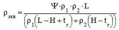
- ρ1 and ρ2 - resistivity soil layers;
- H is the thickness of the upper layer;
- Ψ - seasonal coefficient.
The seasonal factor depends on the climatic zone. Also, it is amended, depending on the number of used electrodes. The indicative values of the seasonal coefficient are from 1.0 to 1.5.
Number of electrodes
The required number of electrodes is determined from the expression:
n = Rz / (K R), where:
- Rz - permissible maximum resistance of the grounding device;
- K is the utilization factor.
The utilization factor is selectable. in accordance with the selected number of ground electrodes, their relative position and the distance between them.
Row arrangement of electrodes
| Quantity electrodes | Coefficient | |
|---|---|---|
| 1 | 4 6 10 | 0,66-0,72 0,58-0,65 0,52-0,58 |
| 2 | 4 6 10 | 0,76-0,8 0,71-0,75 0,66-0,71 |
| 3 | 4 6 10 | 0,84-0,86 0,78-0,82 0,74-0,78 |
Contour placementelectrodes
| The ratio of the distance between electrodes to their length | Quantity electrodes | Coefficient |
|---|---|---|
| 1 | 4 6 10 | 0,84-0,87 0,76-0,80 0,67-0,72 |
| 2 | 4 6 10 | 0,90-0,92 0,85-0,88 0,79-0,83 |
| 3 | 4 6 10 | 0,93-0,95 0,90-0,92 0,85-0,88 |
The calculation of the ground loop does not always give the required value, therefore, it may need to be performed several times, changing the number and geometric dimensions of grounding electrodes.
Grounding measurement
To measure the grounding resistance, special measuring instruments... The right to measure grounding is possessed by organizations with the appropriate permission. Usually these are energy organizations and laboratories. The measured parameters are entered into the measurement protocol and stored at the enterprise (in the workshop, at the substation).

The calculation of the grounding resistance is difficult task, in which it is necessary to take into account many conditions, so it is more rational to use the help of organizations that specialize in this area. To solve the problem, you can make calculations on an online calculator, an example of which can be found on the Internet in the public domain. The calculator program itself will tell you what data should be taken into account in the calculations.
Video
To provide private house necessary structures for electrical safety, use such an important element as protective grounding. It is necessary in order to ward off electricity into the ground along the grounding system consisting of horizontal and vertical electrodes. In this article, we will tell you how to perform a grounding calculation for a private house, providing all the necessary formulas.
What is important to know
The grounding conductor connects to electric board the contour of the structure itself. Below are the diagrams:

When performing grounding calculations, it is important to ensure accuracy in order to avoid impairing electrical safety. In order to avoid mistakes in calculations, you can use special ones on the Internet, with the help of which you can accurately and quickly calculate the required values!
The video below clearly demonstrates an example of calculation work in the Electric program:
This is the method used to calculate the grounding for a private house. We hope the provided formulas, tables and diagrams helped you cope with the work yourself!
Surely you will be interested in: