What can be cooked from squid: quick and tasty
Homemade grinder with an engine from washing machine
After 2.5 months of lack of free time, it, time, began to appear. I decided that I wouldn’t do anything with a knife until I made a little grinder. Otherwise, I will not get myself together again. I started with the selection of the regulating roller. At work, the feed shaft from the dot-matrix printer was lying around for a long time.
On close inspection, it turned out to be an excellent material.
Outside diameter 45 mm. Inner diameter 30 mm. Thickness rubber cover 3 mm. The thickness of the duralumin tube is 4 mm.
I cut off a piece of 40 mm, gave it to the turner, who machined 32 mm places for bearings and, at the same time, slightly machined the barrel.


Bit for drilling holes for sockets. Diameter 80 mm. It was worth 45 NRN. Plus a victorious drill in fat. Light tuning from a turner led to this result


Tape 533 x 75 mm, cut lengthwise / in half.
Fitting

Went into action and a piece of tile

Grinder literally means a grinder. Meat grinder is a meat grinder, rock (stone) grinder is a stone crusher; stick (wood) grinder - garden crusher of branches and twigs into chips. But there is also a completely unambiguous meaning of the word grinder: in mechanical engineering and metalworking it is grinding machine... A useful thing on the farm. For example, it is impossible to manually direct a blunt knife of a meat grinder on a whetstone bar. On a manual knife sharpener - somehow it is possible, having a solid working skill. And on the grinder - no problem. The same applies if you need to grind a complex-shaped part without breaking its profile. Or just sharpen scissors or a professional knife. All kinds of cutters for wood and metal are best used on the grinder too. It is quite possible to design and assemble a grinder with your own hands, without having complex equipment and skills to work on it. In terms of money, this will mean savings of 50-90 thousand rubles. up to 3-6 thousand USD.
To make a grinder yourself, you will need to order a maximum of 4-5 chiseled parts, and it is often possible to do without turning from the side at all. For example, how to make the simplest grinder literally out of trash, see the video below:
Video: DIY belt grinder from trash
Or another option, how to make a grinder stronger and more durable from scrap metal:
Video: scrap metal grinder
Disc or tape? And drive
Almost more varieties of grinding machines are used in industry than lathes. Emery known to all craftsmen - a motor with a pair of grinding wheels (or one circle) - is also a grinder. For yourself, at home, it makes sense to make either a disc end (plate) or a belt grinder. In the first, the abrasive is applied to a rotating hard disk; in the second - on an elastic band around the system of pulleys and rollers. Disc is more suitable for sanding simple wood parts and rough to medium-clean metal parts. On a belt grinder, it is also possible to perform precise and clean finishing of profiled parts of complex shapes, incl. large, see below.
A disc grinder is very simply obtained from the very same emery or a suitable motor in terms of power, see below. It is necessary to order an adapter from the motor shaft for the shank of a grinding disc on a metal base. Or under a chuck, then on the same motor it will be possible to build a mini lathe, see fig.:

A worn-out "plate" is suitable: a disc made of thin (4-6 mm) fibrous plastic is glued to the edge of its side, and an abrasive is applied to it. How to make a face grinder, see next. video clip.
Video: homemade end grinder
The difference between a disc and a belt grinder is not only in the usability. If we take ordinary household crafts, then a drive power of 250-300 W on the shaft is enough for a disc grinder. For small wooden parts - and 150-170 watts. This is a motor from an old washing machine, a straight (conventional) drill or screwdriver. But for a belt grinder, you will need an engine from 450-500 W: three-phase with batteries of starting and working capacitors. If it is supposed to handle a large size, then the motor power is from 1-1.2 kW. Moreover, capacitor banks for both will not cost much cheaper than the engine itself.
Note: The 100-200 W drive uses a mini belt grinder (see below) for precision knife dressing, jewelry grinding / polishing, etc.
A drill or screwdriver as a grinder drive is also convenient because it allows you to quickly change the speed of the abrasive (see below) with a standard speed controller. It is only necessary, firstly, to make a holder for the drill, rigidly fixing the tool. Secondly, an elastic adapter coupling from the drill to the disc shank, because it is difficult to achieve accurate centering without special equipment, and runout will negate machining accuracy and can damage the drive tool.
Drawings of the drill holder for using it as a drive for a home metal-cutting machine are given on the left in the figure:

Since the shock and irregular alternating loads on the drive in the grinder are an order of magnitude lower than, say, in lathe, the drill holder for it can be made of hard wood, plywood, chipboard, MDF, on the right in Fig. The diameter of the mounting (large) hole is along the neck of the drill. It is highly desirable to use a drill without a percussion mechanism and with a steel shell on the neck (for installing the front handle).
Clutch
For the transition coupling, you need a piece of steel rod (not necessarily chiseled) of the same diameter as the shank of the grinder drive shaft, and a piece of reinforced PVC hose (garden irrigation) with a clearance so that it is tightly pulled over the rod and the shank. The length of the "free" hose (between the ends of the rod and the shank in it) is 3-5 cm. The length of the protruding part of the rod should be sufficient for a reliable clamping in the drill chuck. After assembling the coupling in place, the hose on the shank and the rod is tightly tightened with clamps; can be wired. Such a clutch completely counteracts the misalignment of the drive and the driven shaft up to 1-1.5 mm.
The tape is still better
The belt grinder allows you to do everything that the disc grinder does and much more. Therefore, further we will focus on how to make a belt sander with our own hands. Amateurs, focusing on industrial designs, make grinders sometimes very intricate, see fig .:

And this is justified: the design and kinematics of the belt grinder are very plastic, which makes it possible to successfully use improvised materials and old scrap metal. You only need to follow 3 principles:
- Do not do as in the second photo from the left of the picture: the abrasive side of the tape should only touch the workpiece. Otherwise, the abrasive will eat both the bypass rollers and itself. The accuracy and cleanliness of processing during one work step will turn out to be unpredictable;
- The design of the machine should ensure uniform belt tension regardless of the nature of the operation being performed;
- The belt speed must correspond to the nature of the operation being performed.
Kinematics and design
As mentioned above, there are many designs of grinders. Thinking of what and how to build a grinder for yourself, it is better to focus on industrial designs intended for fully mechanized grinding of large-sized profiled parts for accurate and clean grinding: if the propeller blade of an airplane or wind turbine “skins” as it should, then it will cope with any other work.
The kinematic diagrams of grinders for the indicated purpose are given in Fig.:

Basic kinematic diagrams of belt grinding machines (grinders)
Pos. A - the most complex and perfect, with three rocker arms. If the length of the tensioning roller rocker is approx. 2 times less than the working one, then, by adjusting the tension of the springs, it is possible to achieve a uniform tension of the tape during the course of the working rocker by 20-30 degrees up and down. By tilting the bypass rocker, firstly, the machine is readjusted for belts of different lengths. Secondly, in the same way, you can quickly change the belt tension for different operations. The working branch of the belt can be any, except for the one running from the drive pulley to the tension roller, i.e. grinder with 3 rockers is both horizontal and vertical at the same time.
The scheme with a coaxially swinging rocker arm (pos. 2) is simpler, cheaper and in terms of processing accuracy is not inferior to the previous one, if the length of the rocker arm between the axes is at least 3 diameters of the workpiece being machined. To knock down the profile by grinding, the movement of the rocker arms is limited by stops within 10 degrees up and down. The clamping of the tape to the part is most often gravitational, under the weight of a rocker arm with a bypass pulley. The belt tension can be quickly changed within certain limits by pulling the rocker arm up with a weak adjustable spring, which partly compensates for its weight. The grinder of this scheme can work as a grinder for small parts from a sliding table. In this case, the rocker arm is rigidly fixed horizontally, and work surface the belt will be wrapped around the bypass pulley. According to the scheme with a coaxial rocker, for example, the rather popular BTS50 grinder is made. The disadvantages of the scheme are, firstly, the technologically complex rocker arm joint coaxial with the drive shaft. Secondly, the need for an elastic band: if you make the bypass pulley slide spring-loaded, the machining accuracy decreases. This disadvantage when processing small parts is completely eliminated by an additional tension roller, see below.
The scheme with one misaligned rocker arm is rarely used in industry, because in principle, it does not allow achieving uniform belt tension. However, it gives an accuracy that is quite sufficient at home and allows you to build a very good simple grinder.
What's good for what
Now let's see what it is possible to "squeeze" out of a particular scheme from the point of view of an amateur master. And then we'll try to figure out how to make a tape for a grinder ourselves and do without custom-made chiseled parts.
3 rocker arms
Competent amateurs build their grinders just according to the scheme with 3 rockers, on the left in fig. below. The propeller blades do not grind everything, but in this case another advantage of this scheme works: if the grinder is used as a vertical one, then the working branch of the belt is elastic. This allows a skilled craftsman, for example, to direct cutting edges and blades with literal micron precision.

In industrial grinders for home use, the 3-beam scheme is also widely used (center) for the same reasons. Repetition of them yourself in most cases is quite possible. For example, drawings of the KMG grinder, popular abroad, can be downloaded.
Dimensions, however, inch - American machine. For the drive, in any case, it is possible to use an angle grinder drill (on the right in the figure, quite suitable in terms of power) with a homemade pulley and rollers, see below.
Note: if you are going to make a stationary drive, try to get an asynchronous motor at 2-3 speeds from an unusable washing machine with a horizontal tank. Its advantage is low turnover. This makes it possible to make the drive pulley large diameter and thus eliminate slippage of the belt. Ribbon slip in operation is almost certainly a damaged part. Most washers with 2-3 speed 220 V asynchronous motors are Spanish. Shaft power - 600-1000 W. If you come across such, do not forget about the standard phase-shifting capacitor bank.
Coaxial rocker
In their pure form, amateurs do not make grinders with a coaxial yoke. A coaxial hinge is a complicated thing, you can't make an elastic tape yourself, and a purchased one is expensive. Grinders with a coaxial yoke at home are used most often in the version for small precise work from a table, i.e. with a rigidly fixed horizontal beam. But then there is no need for a yoke as such.
An example is a mini grinder, the drawings of which are given in the figure:

Its features, firstly, an overhead bed for the tape (pos. 7), which greatly expands the possibilities of use. For example, the plane of the plane is driven by this grinder with an angle stop literally by itself. In this case, the grinder works, so to speak, like a self-propelled touchstone (emery bar). After removing the bed, we get a grinder with an elastic band for precise grinding / polishing of rounded small parts. Second, the idler shaft (key 12). Having clamped it with a groove with nuts, we get a relatively fixed tension of the tape for working with the bed. And after loosening the nuts, we transfer the grinder to the gravitational belt tension mode for delicate work. Drive - not necessarily through a pulley (key 11). Can be screwed directly past the drive shaft end (key 16) from the drill through the adapter sleeve, see above.
A specialized tool grinder (for example, for pointing and dressing turning tools) generally loses any semblance of the original scheme. They take a high-speed motor for it (power of 200-300 W is enough). The drive pulley is suitably small in diameter. The bypass pulley, on the other hand, is made larger and heavier for inertia. All this together helps to reduce belt runout. The tension roller with the same purpose, plus for greater uniformity of the belt tension, is taken away and spring-loaded with a long, not very strong spring. How to make a grinder for processing cutters, see the video below.
Video: grinder for making cutters
One rocker
In amateur practice, grinders with a misaligned rocker are good because they do not need precise parts at all. For example, hinges can be made from card loops. At the same time, the processing accuracy remains sufficient for ordinary amateur inquiries.
The original scheme in this case is also modified: the rocker arm is turned 90 degrees, carried up and spring loaded, on the left in Fig. It turns out to be a simple vertical grinder. And, importantly, it works without problems with a homemade inextensible tape. Both tension (center) and compression springs can provide belt tension. Its strength is not important as long as the tape does not bend excessively during operation. No adjustments are required during use.

Consumables and parts
The only consumable for a belt grinder is a tape (not counting grease for bearings and joints. The tape can be ordered in the required length (see at the end), but you can also make it yourself from emery cloth on textile base... Highly desirable - flexible, non-impregnated. In general, the procedure for making a tape for a grinder with your own hands is as follows:
- We cut off the workpiece - a strip of the required length and width.
- We prepare a mandrel (not necessarily round) of length along the generatrix slightly less than the length of the tape.
- We circle the mandrel with the workpiece inside out.
- We bring the ends of the workpiece exactly end-to-end and securely fasten.
- Put a piece of a glue stick for a hot glue gun on the joint.
- We heat with a building hair dryer until the glue melts.
- We put a patch of thin fabric on the joint.
- Press with something hard through the Teflon film until the glue hardens.
There are three essential points here. The first is to use a rough PET film with a thickness of 25-50 microns (sold) instead of fabric on a patch. It is very durable, try running your finger over the PET bottle. Not very slippery? A rough PET film cannot be pulled under tension even over polished metal. And instead of a patch, it is better to glue the wrong side of the tape with a continuous strip of PET film with an overlap of 2-3 cm. The runout of the tape will be no more than 0.05-0.1 mm. This is less than from the thinnest calico and even less than the error in the thickness of the blank skin.
Second, put the finished tape into the machine and grind something obscene with it without strong pressure. The scar on the seam will come together, and the tape will not be worse than the branded one.
But the most important thing is that in terms of elasticity, the best glue for gluing a grinder tape is not expensive and difficult to use thermal or assembly, but ordinary PVA. If the tape is pasted over with a lining along the entire length of the wrong side, then its strength for PVA is more than enough. How to peel off the PVA grinder tape, see video
Video: gluing a tape for a grinder with PVA glue
Pulley
The generatrix (side surface in section) of the drive pulley of the grinder must be straight. If you use a drum pulley, then the belt will bend in a trough along its entire length. The rollers do not allow it to slip, see below, but the generatrix of the pulley must be straight.
A pulley for a grinder that is not designed for particularly precise work, firstly, does not have to be chiseled. In the scheme with 3 rocker arms, the runout of the tape from its misalignment will go out on the rollers before it reaches the working branch. In a simple vertical grinder, the belt runout will be sufficiently absorbed by the tension spring. Therefore, it is quite possible to make a pulley for a grinder without a machine, see the video:
Video: drive wheel on a grinder without a lathe
Second, the pulley, rollers and, in general, all the details of a home grinder are perfectly acceptable to be made of plywood. In production, this is certainly not an option, even if the plywood grinder is offered for free with a surcharge: the grinder needs a salary, and the wooden grinder in the workshop will completely wear out before it pays for it and itself. But you won't be driving a grinder at home every day in 3 shifts. And no tape slips over the plywood pulley. Incl. homemade. So you can safely make a grinder pulley out of plywood:
Video: plywood grinder pulley
It is much more important to correctly calculate the pulley diameter based on the motor speed and the required belt speed. Running too slowly will tear the material to be cut; too fast - it will be erased by itself, without really processing anything. In which case what tape speed is needed is a special conversation, and very difficult. In general, the finer the abrasive and the harder the material being processed, the faster the belt should move. How the belt speed depends on the diameter of the pulley and the speed of the motor, see fig.:

Fortunately, for most abrasive-material pairs, the allowable belt speed limits are quite wide, so a grinder pulley can be selected more easily:
Video: which wheel is needed for a belt grinder
Rollers
Grinder rollers, oddly enough at first glance, are its most crucial parts. It is the rollers that keep the tape from slipping and provide its uniform tension across the width. Moreover, there can be only one video in kinematics, see, for example, the video above about a grinder for cutters. Only casters-barrels can cope with this task, see below. But the "trough" of the tape after any roller must straighten out before it reaches the working area.
Rollers with flanges (sides, flanges) will not hold the tape. The point here is not only and not so much with the misalignment of the axes of the rollers: the grinder belt, in contrast to the drive belt, must withstand, without sliding, the loads from the workpieces. If you make rollers with flanges, then, slightly touched something to the tape, it will crawl onto the flange. In the grinder, type 3 barrels must be used (highlighted in red on the left in the figure).

There are also given the dimensions of rollers Type 3. It is advisable to take the diameter of the rollers no more than 0.5 of the width of the tape (so that the "trough" does not go far), but not less than 20 mm turned steel and not less than 35-40 mm plywood. The tension roller (the probability of slipping of the tape from it is greatest), if the working branch of the tape does not come off it, can be 0.7-1.2 in diameter of its width. Plywood rollers are made in the form of a thick shell into which the bearing is pressed; then the roller is pushed onto the axle (in the center in the figure) and machined clean, see eg. track. video:
Video: barrel roller for grinder
Not every turner can grind a profile roller exactly according to GOST. Meanwhile, there is a way to make rollers for a grinder without significant difficulty. The same garden hose reinforced with PVC will help out, on the right in fig. previously. On the blank of the roller with a straight generatrix, its segment is tightly pulled and cut with a margin along the edges to the thickness of the hose wall. The result is a roller with a complex profile of the generatrix, which holds the tape even better and gives a smaller "trough" of it. Don't believe me? Try to get to the graveyard of planes or missiles and dig into them. You will find rollers with exactly the same lateral profile. It's just that the mass production of rollers of a complex profile is much more expensive than Type 3 barrels.
And another option
All critical parts of the grinder - one-piece belt, anti-slip coated pulleys, rollers - can be purchased separately. They will not cost so cheaply, but still not in thousands of foreign and not in dozens of native "leather jackets". The rest of the grinder parts, either flat or from professional pipes, are made using a conventional bench drill or drill. Here's where to order grinder parts:
- //www.cora.ru/products.asp?id=4091 - tape. Lengths and widths are made at the request of the customer. Provide advice on abrasives and processing modes. The prices are reasonable. Delivery time - questions to Ruspochta.
- //www.equipment.rilkom.ru/01kmpt.htm - spare parts (components) for grinding machines. There is everything, the prices are divine. Delivery - see prev.
- //www.ridgid.spb.ru/goodscat/good/listAll/104434/ - the same, but foreign production. Prices are more expensive, delivery is the same.
- //www.pk-m.ru/kolesa_i_roliki/privodnye_kolesa/ - drive wheels. Suitable for grinder can be found.
- //dyplex.by.ru/bader.html, //www.syndic.ru/index.php?option=com_content&task=view&id=36&Itemid=36 - spare parts for grinders. They don't make tapes to order - choose from the catalog. Rollers without axles; axles are sold separately. The quality is impeccable, but everything is very expensive. Sending - within 2 weeks to the border. Then - their customs, our customs, Ruspochta. Total approx. 2 months It may not get through if some local bureaucrat considers the goods to be sanctioned. In this case, there are no problems with the return of the payment due to the complete absence for an ordinary citizen of real opportunities to receive such. (2 estimates, average: 5,00 out of 5)
If you have an old washing machine engine, you already own many useful machines that you can assemble from it. In this tutorial, we'll show you how to make a small one out of such an engine. Such a machine will be an excellent addition when grinding small items. For example, it is convenient to sharpen drills on it, and wood is generally easy to process.
In the assembled machine, the author used a 180 watt motor with 1350 rpm. This engine is too weak for such machines, so you need to use more powerful motors. A 300 watt motor should be enough. RPM also plays a big role if you are thinking of processing steel, for other materials such as wood and plastic, RPM is not important. Everything is going to be quite simple, but you will need the services of a turner to grind the pulleys of the machine. However, impellers can also be made of plywood, and the same engine can be used as a lathe. Let's consider in more detail how to assemble such a machine!
Materials and tools used
List of materials:
- steel corner, plates, sheet steel;
- bolts, nuts and washers;
- the engine from the washing machine;
- sanding belt;
- furniture gas back-up (for tensioner);
- impellers (we order a turner made of steel or aluminum).
Tool list:
- welding machine;
- grinder;
- drilling machine;
- spanners.
Manufacturing process:
Step one. We deal with the engine
First of all, we will prepare the engine, we will need to weld a bracket for it. For these purposes, we use sheet steel. We fasten the bracket to the engine using bolts and nuts or screw it to the studs that tighten the engine. The engine bracket is then welded to the base or bolted with nuts.


Step two. Assembling the machine frame
The base of the machine is made from a piece of sheet steel. The thickness of the metal must be such that it does not bounce or bend. We drill holes in the corners of the sheet and fasten the legs, they must be rubber so that the machine vibrates less. We also assemble the rack from sheet metal, cut out the desired shape and then weld it to the base. We strengthen the rack by welding a corner or another piece of metal.


Step three. Pulleys
Pulleys or impellers are hardened by a turner, they are made of steel. Aluminum and other metals can be used. And if the machine is not powerful, then such wheels can be completely made of plywood by gluing several layers. The author fixes the lower drive wheel on the shaft with a screw, a hole is drilled in the wheel under it and a thread is cut.
And the upper wheel has two bearings, between which a spacer sleeve is installed. The upper wheel is clamped with a nut.


Step four. We start assembling the machine
The assembly of the machine consists in the assembly of the upper unit. The drive wheel is an adjustment wheel, its horizontal angle must be changed so that the belt can be centered. The whole thing is assembled from sheet metal and bolts and nuts.
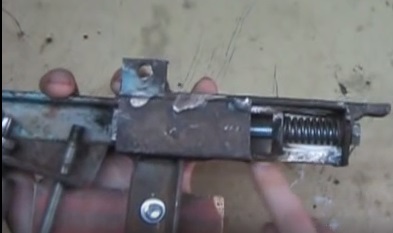
You will also need to install a tensioner, which the author uses as a furniture gas backpressure. This element can be replaced with a spring or an old pump can be remade.
We also fasten the thrust platform, into which we will abut the product and the handcuff. Both planes are held by bolts with nuts, which allows them to be adjusted or removed.


That's all, the machine is ready, you can try to turn it on. The author has not yet made a switch, everything is started by plugging the plug into the outlet. The machine works, but the belt moves slowly, and the power is not enough, the machine stops if you press hard on the belt. However, the machine is quite suitable for processing any small products or for sharpening tools. By installing a more powerful engine here, you can get a pretty decent machine.
That's all, the project is over. Good luck and creative inspiration if you decide to repeat it. Do not forget to share your best practices and
Washing machines often fail while keeping their engine fully functional. Its power and actual rpm are well suited for using this part in the manufacture of homemade machine tools. As it turned out, such an electric drive is also perfect solution for installation on a homemade grinder.

Materials used
It took not so much to make:- motor from a typewriter;
- his own starting capacitor;
- part of the sheathing of the machine;
- 4 rubber feet from the washer;
- plywood sheet;
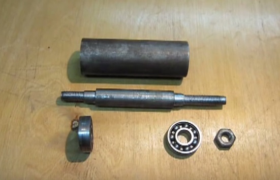
- a 5 cm section of a thick-walled tube with an inner diameter of 14 mm;
- 2 identical bearings;
- glass sealant;
- sheet metal with a cross section of 8 mm;
- corner 63x63 mm;
- profile pipe 40x40 mm;
- profile pipe 30x30 mm;
- extended nut;
- steel strip with a cross section of 10 mm;
- furniture gas shock absorber;
- power button;
- plastic plugs 30x30 and 40x40 mm;
- bolts and nuts M12, M10, M6 and M5.


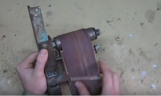
The process of making a grinder from a washing machine
To begin with, I made tension rollers.
These are factory made metal ones. Ours will be homemade, wooden. For their manufacture, moisture-resistant plywood is suitable, its thickness is not so important.

From it you need to make pancakes, which will then stick together into a roller. First, I install a 102 mm diameter wood crown on the drill. Cutting out 9 plywood pancakes for the drive roller. The number of circles depends on the thickness of the existing plywood and the width of the tape that will then be used.

Now the pancakes need to be glued. First, you will have to grind them a little in order to remove chips from the crown. I grease the side of the circles with PVA glue and form a wide multilayer roller. For normal gluing, I fix the workpiece under a press.

While the drive roller is drying, the drive roller can be made. A 64 mm crown is used for it. Again, using a drill, I cut out 9 pancakes from the same plywood and glue under the press.

To prevent delamination of the rollers after they dry, I made 2 side holes in them and pulled everything together with a couple of screws on each side.
I balance the rollers in a lathe, grind down irregularities a little and achieve the smoothness of the workpieces.

An adapter must be made to attach the drive roller to the engine shaft. For this, a section of a thick-walled tube is used.

In most cases, a pipe with an inner diameter of 14 mm will be required. To press the tube on the shaft of the electric motor, I drill a hole and cut the M5 thread. At the second end of the tube, I weld on an M12 bolt.


I expanded the hole of the drive roller halfway to fit the tube. The rest of the narrow part will include the thread from the M12 bolt.
A pair of bearings must be placed in the driven roller, one on each side. Their size is not so important, you can use any, the main thing is that of a suitable inner diameter. Preparing bearing seats on a lathe.


To make the surface of the rollers smoother, I decided to cover them with glass glue. To do this, I fix them one by one in a lathe, and evenly coat them along the perimeter and ends.


Now you need to make a bed for installing the electric motor. I use as a basis a metal sheet section of 8 mm. I cut out a rectangle with sides 220 by 310 mm.

For direct mounting of the engine, you will need 2 corners. I prepare lengths of 130 mm. The 63rd corner fits perfectly under the electric motor.

I lay the steel plate on a flat surface, put the corner and the engine, then I make the markings for drilling the mounting holes with a 6 mm drill.

So that in the future the corner does not interfere with the drive roller fixing bolt, you need to select the metal near the shaft. The easiest way is to cut out a small triangle.


I mount the corners on the electric motor using four M6 nuts with a press washer.

I install the motor with the mountings in place, make the markings and weld the corners to the sole of the machine.

Cut off from shaped pipe 40x40 workpiece 300 mm long. I make another piece of the same length, but already from a 30x30 mm profile pipe.

Now we need to make the belt adjustment mechanism. To begin with, I take an elongated nut and grind its edges.

I weld it up to a steel strip with a section of 10 mm. I drill a hole in the strip and cut the M10 thread for the bolt on which the driven roller will be fixed.

Then from a previously cut off square pipe 30x30 I welded an L-shaped workpiece. I welded nuts to it to fix the strip made. I also fixed a nut with a bolt on the perpendicular wall of the square opposite the head of the bolt on which the driven roller will be mounted. By twisting or unscrewing a short bolt, it will be possible to change the angle of the roller, thereby adjusting the machine.


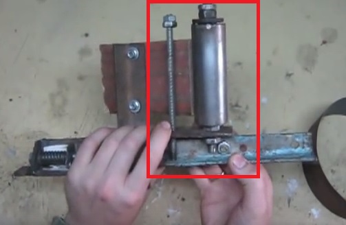
I put a 40x40 vertical profile pipe on the machine platform and weld it on. At the same time, I try on in place so that the driven roller stands opposite the leading one, which in turn is fixed on the motor shaft.

To ensure smooth belt tension, you need to install a gas furniture shock absorber between the 40x40 vertical pipe and the 30x30 L-shaped roller holder.


I make the support platform for the machine from the available materials. Using a small section of a 40x40 profile pipe and a 63rd corner. I made a cutout on the pipe to increase the welding area. The corner is attached with bolts, as it will need to be removed for servicing. I made all the blanks without preliminary size, just adjusting them in place.


And now I am preparing a table to stop the workpieces being turned. For this I use the same sheet metal with a cross section of 8 mm. The width of the table was made 80 mm.
Preparing the base for the table. To do this, I take a 40x40 pipe with a length of 120mm. I drill a hole in it, hone the butt end in a semicircle and cut the M10 thread. I make small lugs out of sheet metal. They will act as loops. I weld the ears to the countertop.

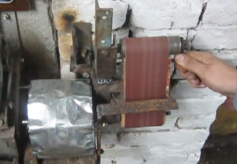
If you have an unwanted washing machine that could not be sold, it can be used profitably. You can make a homemade sander from a washing machine engine. Such a device is called a grinder.
It has advantages over grinding machines - it allows you to conveniently process the ends of products, as well as small parts. Find out how to assemble a machine with your own hands in our article.
When the machine is used
The grinder is used for the final treatment of parts from roughness - before painting or varnishing. Also for leveling defects and imperfections on surfaces.
The machine will allow you to quickly and efficiently cope with the work. In addition, tapes of various grain sizes go to it, so that the scope of application is quite wide. Depending on the choice of belt, you will be able to process products from:
- wood;
- become;
- non-ferrous metal.
Using a homemade product from an engine from washing machine it will be convenient to grind parts of various shapes, which you cannot do hand tool... For example, triangular, pipe, flat and round objects.

Preparatory work
You will need to make a movable element with your own hands, along which the tape will move. If you buy it separately for assembling a structure, then it will cost about the same amount as a new machine.
What parts are needed for work:
- corners: one 40 cm long and two 15 and 25 cm;
- 2 long bolts and a few regular bolts, nuts, washers, spring;
- hairpin;
- a piece of metal measuring 30x100 mm.
What tools will be needed:
- lathe;
- drill;
- welding machine;
- pliers;
- open-end wrenches;
- Bulgarian.
You also need parts that can only be made on a machine or ordered in a workshop. It:
- roller;
- bearing;
- sleeve;
- screw;
How to assemble a grinder from a washing machine motor: instructions
Now take the prepared corners. Connect the corners by welding, as seen in the photo below. Weld two small metal plates with bolt holes parallel to the bottom.
A bolt with a spring put on it, installed in the end hole of the structure from the corners, will help to adjust the belt tension on the machine. Make a hole at the top of the corner for the short bolt. Screw in this place the short part of the corner, which is not fully secured with the bolt. The short section should move, allowing the belt tension to be changed.
Then install the roller with the bearing mechanism. Do not tighten the roller on the corner too much, it should rotate freely. Secure one end of the roller with a nut, and weld the other welding machine to the corner.
Install the stud. To do this, make an additional hole in the corner under the roller. After threading the hairpin, secure it with two nuts on one side. When installing the stud, make sure that it enters along the thread.
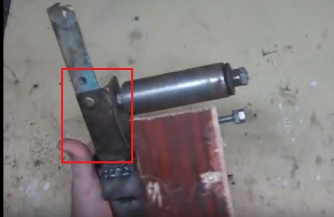
As you can see in the photo above, there is another element in the design. This is a corner with a piece of chipboard, which is fixed with short bolts. It is for your safety. The tension on the belt is done with a pin, so your hands will be close to the fast moving belt. This bar will protect your hands from damage.
How to connect a motor
It remains to connect the electric motor. It is advisable to use an asynchronous engine from an automatic washing machine. The power can be from 200 to 300 watts, and the speed of revolutions from 1500 to 3000 per minute. Consequently, the performance of the belt will depend on the characteristics of the motor.
It is good if the motor has a long enough shaft. But if this is not the case, then you need to increase it yourself. Here you need a special wood bushing made on a machine. The sleeve is put on the motor shaft, after which the tape is put on it.

So that the tape does not move during operation, but is located in the middle, you need to make the central part of the sleeve 2-3 mm larger.
Installing the Ribbon
You can buy a special tape or make it from an emery cloth. Its width should be no more than 200 mm. Cut the blade into strips of the appropriate length. Now the strips need to be connected. Use only special glue. Then proceed like this:
- Put glue on the pieces when stacking them butt-to-joint.
- Lay a piece of cloth on top and press firmly.
- Then cover with a piece of paper and secure with a hot iron.
- Trim off excess fabric around the edges.
Since the tape will have a strong impact, the connections must be made with high quality.
When putting on the tape on the grinder, make sure that the overlapping seam does not bulge during operation.
How to adjust a sander
The belt is adjusted with a hairpin, which is installed in the structure homemade machine... By twisting and unscrewing the pin, you affect the degree of pressure (tension) of the tape.
Here you need to be careful: if you work at high speed with little tension, the processing may be of poor quality, with missing sections. If you reduce the speed and tighten the belt harder, you can ruin the product.
Also select the grit of the abrasive according to the material being processed.
Having figured out the details of the work, you will acquire a useful technique for home use.